Slice Design Card Hack
My other half acquired a funky Slice scrapbooking machine - a die cutter with LCD screen.
A nice little reverse engineer challenge!
Contents
Basic File Structure
.
├── 11
│   ├── 11-11
│   │   ├── 11-11-17
│   │   │   ├── 11-11-17.DAT
│   │   │   ├── 11-11-17.DN2
│   │   │   ├── 11-11-17.DN3
│   │   │   ├── 11-11-17.DN4
│   │   │   ├── 11-11-17.DN5
│   │   │   ├── 11-11-17.DN6
│   │   │   ├── 11-11-17.DN7
│   │   │   ├── 11-11-17.DN8
│   │   │   ├── 11-11-17.dot
│   │   │   └── fdata.txt
│   │   ├── 11-11-17.DAT
│   ├── 11-17.DAT
<snip>
│   │   ├── calbrate
│   │   │   ├── calbrate.DAT
│   │   │   ├── calbrate.dn8
│   │   │   ├── calbrate.DOT
│   │   │   └── fdata.txt
│   │   ├── calbrate.DAT
│   │   └── fdata.txt
│   ├── 11-18.DAT
│   └── fdata.txt
├── 11.DAT
├── 12
│   └── fdata.txt
├── 12.DAT
├── fdata.txt
├── MSPBOOT.BIN
├── readme.txt
└── Utils
    ├── ALIGN.DAT
<snip>
    ├── SPLASH1.dat
    └── WORKING.DAT

174 directories, 1819 files
Files
Card filesystem structure is FAT32, boot sector appears to be a standard MSDOS 5.0 one, even referencing NTLDR, hope they paid M$ for licensing!
MSPBOOT.BIN is the initial boot image (kernel?) and links to files in the /Utils folder which are mostly on screen images (.dat) and the calibration data.
The rest of the structure requires fdata.txt in root of al dirs. It acts as way to determine the immediate sub directory structure, contains the count and names of the directories under where it exists.
| file | description | columns for correct hex viewing |
|---|---|---|
| /11/11-11/11-11-17/11-11-17.DAT | Image on 'size' choosing screen | 12 |
| /11/11-11/11-11-17/11-11-17.dot | Image on 'size' choosing screen, showing starting point | 12 |
| /11/11-11/11-11-17/11-11-17.DN2 | Cutting pattern at size X | 4 ? |
Hardware
Screen
Screen is 128x128 pixels. It has a greyscale consisting of black (on),dark grey,light grey and off.
Image file fullscreen sized, (e.g. /Utils/SPLASH1.dat) , represented by hex 32 columns by 128 rows.
Decyphering image .dat LCD hex file
The splash screen in /Utils/SPLASH1.DAT
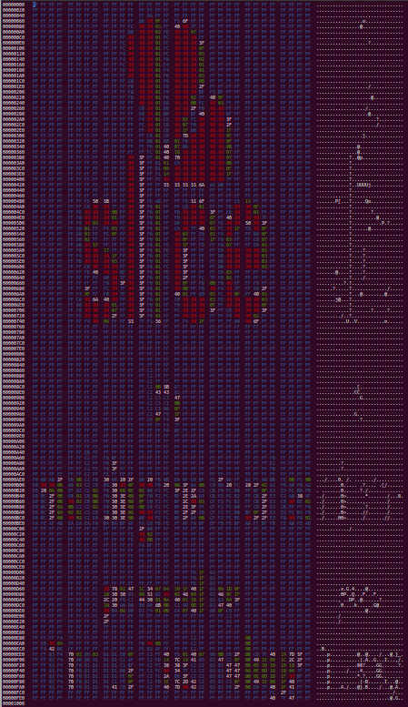
To display this so it makes sense (took a lot of fiddling with to work out!), open with hexedit like this. The colouring helps greatly trying to see an image, although as you can see it doesn't colour everything so it looks somewhat odd.
$ hexedit --color /media/81830C03/Utils/SPLASH1.dat
- Note, this is a fullscreen image, (the smaller icon type ones are a bit different) and takes 4096 bytes. This encodes the 128x128 pixel screen.
- Note, there are 128 rows x 32 columns (each column hex byte = 4 pixels), hence 128 x (32x4) = 4096 bytes.
Each horizontal (hex) byte in (fullscreen) mode = 4 pixels.
Each pixel state is calculated from 2 bits, calculated in binary as;
00 = on (black) 01 = dark grey 10 = light grey 11 = off (white)
Creating a small example....
| bit1 | bit2 | bit3 | bit4 | sum binary = hex (byte) |
|---|---|---|---|---|
| 10 | 11 | 01 | 00 | 10110100 = B4 |
| 01 | 00 | 11 | 11 | 01001111 = 4F |
| 00 | 10 | 11 | 01 | 00101101 = 2D |
i.e. the third row, first value byte of the .dat file (if looking at it in a 32(cols) x 128(row) view in a hex editor) would be "2D" and create the 4 pixels on the screen as per the third row of the image above.
Another example could be imagining the 32nd column (end one in 32x128 view) - if the value was B4, the last 4 pixels on the right would be as the first row in the image above.
- Note, All these pixels referenced in above example, in the actual splash screen, are "FF". This is 11111111 in binary, [representing the state of 4 pixels](11=off,11=off,11=off,11=off), hence its uncoloured on the splash screen.
Creating replacement pictures
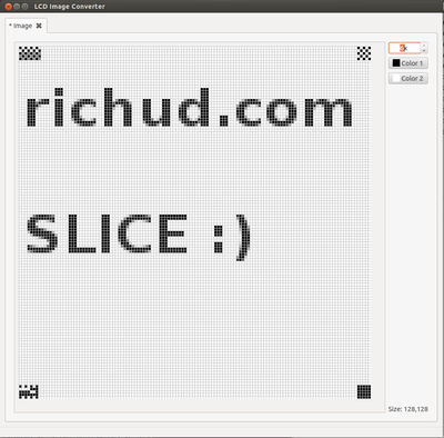
Having understood how it worked eventually (having no prior knowledge about LCD screens!) It became obvious hand editing wasn't going to cut it! Turns out software existed for generating asm or c code, which became enough to do what I needed.
I tried FastLCD and LCDAssistant, but they didnt work properly. LCDAssistant didnt have the right encoding options and FastLCD had the correct options but for whatever reason seemed to encode part of an image and then screw up the output. Tried lots of image types with various options but it never worked properly.
I eventually came across this that works and is in fact much better than the others. (it comes with compiled binaries that work in Windows (and Wine), or can compile from source in linux. (This was done in Ubuntu 12.04)
http://code.google.com/p/lcd-image-converter/ Thanks go to Vladimir for compilation tip.
sudo apt-get install g++ git qt4-qmake libqt4-dev
git clone https://code.google.com/p/lcd-image-converter/
cd lcd-image-converter
#generate version-included.txt
./version-gen.sh
#generate translation file
lrelease resources/lcd-image-converter-ru.ts resources/lcd-image-converter-ru.qm
qmake
make
#run directly
./_linux/release/lcd-image-converter
Brief instructions at time of writing (git-commit-info 0421b4d Tue Jul 24 23:11:14 2012). It is under development so these may change as interface changes):
When it opens, goto 'New Image', OK
Image > Import, open your 128x128 image up, it takes many formats.
Options > Converions, just need to change it from monochrome to greyscale, rest default
File > Convert, save it out as out.c (for this example)
Now this needs filtering/parsing/converting to get a binary hex file from the C source code, this one liner does it in one go and writes the file directly to the card.
grep -Eo "0x[0-9a-f]{2}" out.c | grep -Eo "[0-9a-f]{2}" | tr -d "\n" | xxd -r -p > /media/22D0B017/Utils/SPLASH1.dat
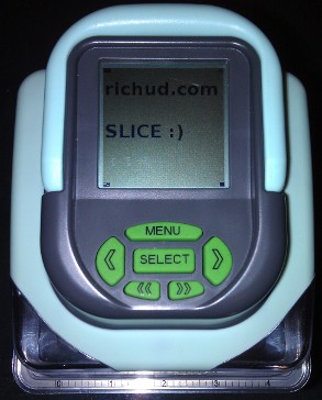
Final outcome :)
Decoding the Stepper Motor Machine Code .dn files
Headings
The first ~16 bytes determin the start position amongst other things. By header I just mean the first bit of machine hex code where 'movement' occurs prior to the knife coming down (00 30).
To yank the first 22 header bytes out to compare;
find ./ -iname "*DN*" -print -exec xxd -c 22 -g 1 -l 22 {} \; | sed ':a;N;$!ba;s/\n0/\t/g' | sort
These are the headers from the basic essentials 1 design card, shapes menu. Circle (11-11-11), square(11-11-12) and triangle(11-11-13) respectively.
.dn2 is 1 inch, each number representing a 1/2 inch step, up to .dn8, 4 inches. The 'size' displayed on the Slice is determined purely by file extension.
Assuming looking from bottom up. (matters for CW ,CCW)
./11/11-11/11-11-11/11-11-11.DN2	000000: 0d a0 0c b0 c8 51 c3 81 90 92 c8 51 c0 41 2e 52 00 30 01 61 02 71  .....Q.....Q.A.R.0.a.q
./11/11-11/11-11-11/11-11-11.DN3	000000: 0d a0 0c b0 c8 51 c4 81 79 92 c8 51 be 41 e7 51 00 30 01 71 01 61  .....Q..y..Q.A.Q.0.q.a
./11/11-11/11-11-11/11-11-11.DN4	000000: 0d a0 0c b0 c8 51 c5 81 62 92 9f 51 bc 41 00 30 01 61 01 71 01 61  .....Q..b..Q.A.0.a.q.a
./11/11-11/11-11-11/11-11-11.DN5	000000: 0d a0 0c b0 c8 51 c5 81 4c 92 57 51 b8 41 00 30 01 61 01 71 01 61  .....Q..L.WQ.A.0.a.q.a
./11/11-11/11-11-11/11-11-11.DN6	000000: 0d a0 0c b0 c8 51 c6 81 35 92 10 51 b3 41 00 30 01 61 01 71 01 61  .....Q..5..Q.A.0.a.q.a
./11/11-11/11-11-11/11-11-11.DN7	000000: 0d a0 0c b0 c8 51 c7 81 1e 92 c8 50 ab 41 00 30 03 61 01 71 01 61  .....Q.....P.A.0.a.q.a
./11/11-11/11-11-11/11-11-11.DN8	000000: 0d a0 0c b0 c8 51 c8 81 07 92 81 50 99 41 00 30 01 61 01 71 05 61  .....Q.....P.A.0.a.q.a
./11/11-11/11-11-12/11-11-12.DN2	000000: 12 a0 0c b0 c8 51 cb 81 87 92 c8 51 75 41 02 52 00 30 02 71 01 60  .....Q.....QuA.R.0.q.`
./11/11-11/11-11-12/11-11-12.DN3	000000: 12 a0 0c b0 c8 51 d1 81 6c 92 aa 51 36 41 00 30 01 61 01 71 01 60  .....Q..l..Q6A.0.a.q.`
./11/11-11/11-11-12/11-11-12.DN4	000000: 12 a0 0c b0 c8 51 d7 81 50 92 5a 51 d7 40 00 30 01 61 02 71 01 60  .....Q..P.ZQ.@.0.a.q.`
./11/11-11/11-11-12/11-11-12.DN5	000000: 12 a0 0c b0 c8 51 dd 81 35 92 18 51 47 40 00 30 03 61 01 71 01 60  .....Q..5..QG@.0.a.q.`
./11/11-11/11-11-12/11-11-12.DN6	000000: 12 a0 0c b0 c8 51 e4 81 1a 92 f2 50 86 4d 00 30 04 61 01 71 01 61  .....Q.....P.M.0.a.q.a
./11/11-11/11-11-12/11-11-12.DN7	000000: 12 a0 0c b0 c8 51 ec 81 ff 91 f3 50 93 4c 00 30 01 61 01 70 04 61  .....Q.....P.L.0.a.p.a
./11/11-11/11-11-12/11-11-12.DN8	000000: 12 a0 0c b0 c8 51 f4 81 e4 91 1c 51 c6 4b 00 30 01 61 01 70 05 61  .....Q.....Q.K.0.a.p.a
./11/11-11/11-11-13/11-11-13.DN2	000000: 18 a0 15 b0 c8 51 c7 81 6b 92 c8 51 c7 41 6b 52 00 30 07 61 01 71  .....Q..k..Q.AkR.0.a.q
./11/11-11/11-11-13/11-11-13.DN3	000000: 18 a0 15 b0 c8 51 ca 81 42 92 c8 51 ca 41 42 52 00 30 09 61 01 71  .....Q..B..Q.ABR.0.a.q
./11/11-11/11-11-13/11-11-13.DN4	000000: 18 a0 15 b0 c8 51 ce 81 19 92 c8 51 ce 41 19 52 00 30 0a 61 01 71  .....Q.....Q.A.R.0.a.q
./11/11-11/11-11-13/11-11-13.DN5	000000: 18 a0 15 b0 c8 51 d2 81 f0 91 c8 51 d2 41 f0 51 00 30 0c 61 01 71  .....Q.....Q.A.Q.0.a.q
./11/11-11/11-11-13/11-11-13.DN6	000000: 18 a0 15 b0 d7 81 c8 91 c8 51 d7 41 00 30 01 61 01 71 0a 61 01 71  .........Q.A.0.a.q.a.q
./11/11-11/11-11-13/11-11-13.DN7	000000: 18 a0 15 b0 dd 81 9f 91 9f 51 dd 41 00 30 01 61 01 71 0c 61 01 71  .........Q.A.0.a.q.a.q
./11/11-11/11-11-13/11-11-13.DN8	000000: 18 a0 15 b0 e4 81 76 91 76 51 e4 41 00 30 01 61 01 71 10 61 01 71  ......v.vQ.A.0.a.q.a.q
Example 2 inch circle
File : ./11/11-11/11-11-11/11-11-11.DN4 Header : 0d a0 0c b0 c8 51 c5 81 62 92 9f 51 bc 41 00 30
| byte range | code | amount of | action | output action |
|---|---|---|---|---|
| 0x00 to 0x04 | 0f a0 0e b0 | nothing | 'design' reference? | n/a |
| 0x05 to 0x06 | c8 51 | (c8) ~4/5 | (51) ~1/2 knife out | ~1/2 knife out |
| 0x07 to 0x08 | c2 81 | (c2) ~4/5 | (81) ~60° turn CW | ~45° turn CW |
| 0x09 to 0x0A | 88 92 | (88) ~1/2 | (92) ~1/4 knife out, STOP | ~1/8 knife out, STOP and wait for green button. |
| 0x0B to 0x0C | c8 51 | (c8) ~4/5 | (51) ~1/2 knife in | ~1/2 knife in |
| 0x0D to 0x0E | c2 41 | (c0) ~4/5 | (41) ~20° turn CW | nothing ? |
| 0x0F to 0x10 | 88 52 | (88) ~1/2 | (52) full knife out | ~1/2 knife out |
| 0x11 to 0x12 | 00 30 | null | knife down | knife down |
Decode Table
This is what the machine byte codes (hex codes) represent, values are approximate and some of the header functions are probably not quite right as the blade movement seems somewhat relative to its current position. (Quite frankly it took ages and I got fed up trying to work out the minutia as it's a bit pointless.)
All that really matters is one turn and one blade movement to get a starting point - I dont know why they contain lots of unnecessary movement. The only sensible one is the calibration one that dispensed with it.
However the main codes that cut the patterns are the 60/61 and 70/71.
| hex | function | travel (at full amount, FF) | direction | notes |
| 0 | none | n/a | n/a | ignored in code |
| 20 | knife up | n/a | n/a | |
| 30 | knife down | n/a | n/a | |
| 40 | turn | 30° | CW | only seems to function if before other turn |
| 41 | turn | 55° | CW | " |
| 49 | turn | 260° | CW | " |
| 4A | turn | 280° | CW | " |
| 4B | turn | 305° | CW | " |
| 4C | turn | 330° | CW | " |
| 4D | turn | 355° | CW | " |
| 4F | turn | 405° | CW | " |
| 50 | knife | ~1/8 | out | possibly depends on current? |
| 51 | knife | ~1/2 | in/out | depends on current blade position |
| 52 | knife | full | out | possibly depends on current? |
| 60 | turn | 30° | CW | used for design cut |
| 61 | turn | 30° | CCW | used for design cut |
| 62 | turn | 30° | CW | not used |
| 70 | knife | ~1/4 | out | used for design cut |
| 71 | knife | ~1/4 | in | used for design cut |
| 72 | knife | ~1/4 | out | not used |
| 80 | turn | 30° | CW | |
| 81 | turn | 60° | CW | |
| 82 | turn | 80° | CW | |
| 90 | knife, stop, wait start | ~1/8 | out | used at start |
| 91 | knife, stop, wait start | ~1/2 | out | used at start, ignore post knife movement? may depend on current blade position |
| 92 | knife, stop, wait start | full | out | used at start |
| F0 | end (in all files) | doesnt actually do anything |
If anyone wants to rip their machine apart to find out what the controller chip is please let me know! There are convertors from .bmp to gcode, then need to convert this to the chips machine code hex, with something like https://github.com/grbl/grbl/
Comments
blog comments powered by Disqus


