FT232R BitBang 433MHz Energenie Power Socket
Contents
- 1 Intro
- 2 Software OLS and GTKWave
- 3 Signal Logic Decode
- 4 Decode Energenie Remote
- 5 Decode table for Remote, code 4514
- 6 Step 1 Test setup receiver and sender with Raspberry PI
- 7 Step 2 Test Setup with FT232RL-RS232 USB Adapter
- 8 Building FTDI-FS1000A device
- 9 C Code
- 10 README
- 11 Example
- 12 Comments
Intro
There seemed to be quite a few sites about controlling 433MHz power sockets with Audrino and Raspberry PI's but I wanted to control one from a server and wanted it as simple as possible. I came across http://hackaday.com/2009/09/22/introduction-to-ftdi-bitbang-mode/ and wondered if it was possible to bitbang it. The FTDI libs should be with any distro and it doesn't need Python.
(Basically this server is attached to the internet via a flakey router that hangs sometimes and we needed a way to get it to reboot. A simple cron task on the server every few mins pings google's DNS server - if all pings fail it powers routers socket on and off, simples!)
Software OLS and GTKWave
I finally had an excuse to buy myself a Bus Pirate - mine was from Seeed studio, so no fake chips!
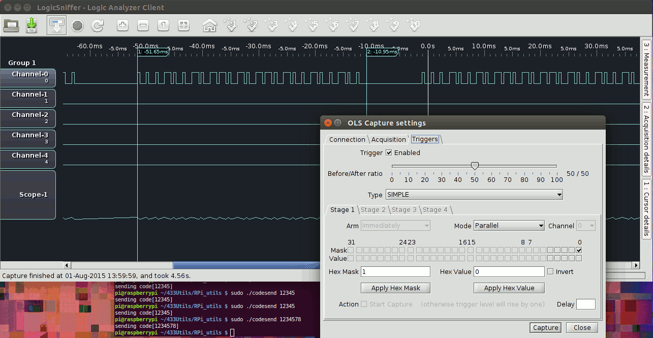
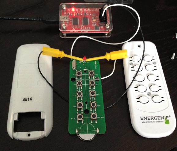
Need to hook a probe from GND and CI then set it up in OLS as per below. CI is 'mask 0' when you set the trigger up. (I was reluctant to break open the remote to begin with but in hindsight I would do this first and stick the probes across the LED (as below). This is most reliable way to get your setup working and get your head around what is going on)
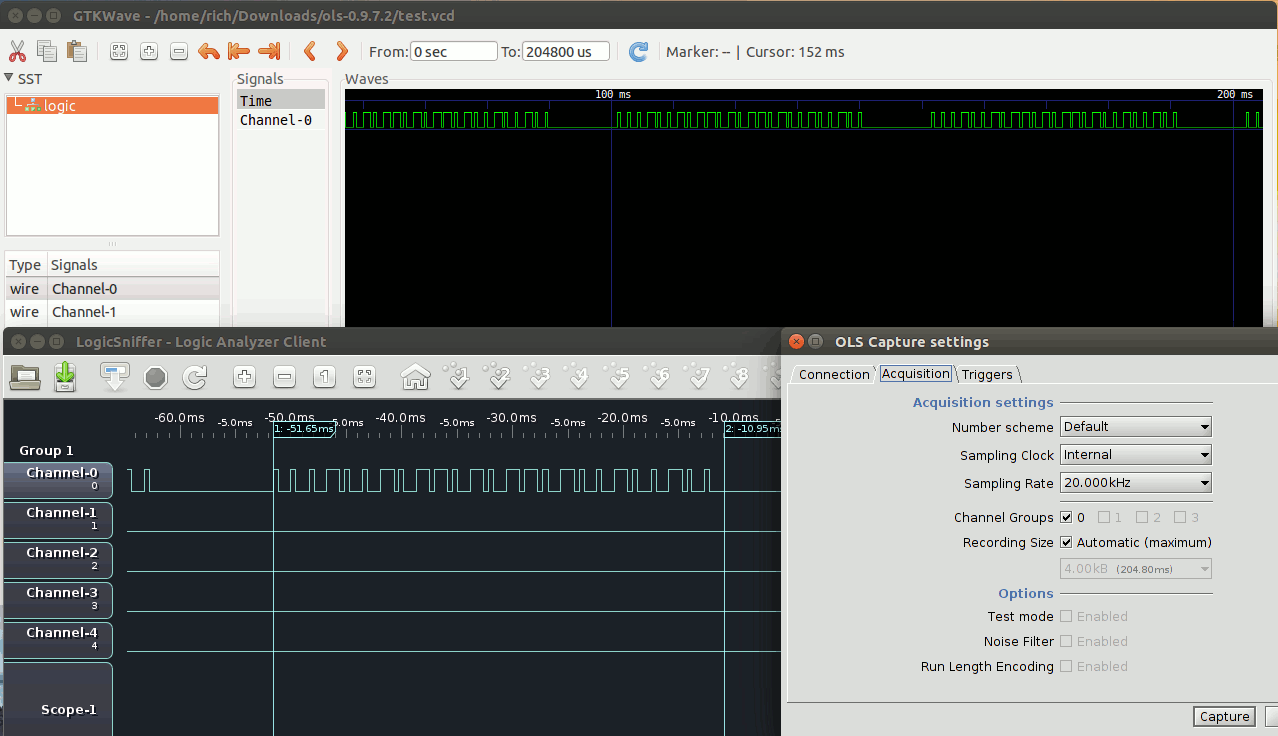
Sampling at 10kHz will give you overview of all the packets and 50kHz is good for measuring one packet.
In a nutshell you set up OLS to the bus pirate, pick sample rate , enable the trigger on mask 0 and hit capture. Assuming your probes are across something like the remotes LED , a second after pressing a button on the remote you should get a wave form like here.
In the screenshot above I had the FS1000A hooked up to my RasPi and was using codesend, hence the long pulses.
- After a lot of confusion I realised the timings are slightly different at different sampling frequencies in OLS, so I just picked one (50kHz) and then based what I was doing on those values.
- I initially had it hooked up to a raspberry PI and used codesend and RFSniffer to send and receive to work out the codes, but in hindsight you can skip this and hook directly to the remote. I did find rfsniffer to be more fussy than the actual plug socket though when timings are not right, so it is a good thing to check with.
- codesend generated on/off pulses about twice as long as the original remote, but it still worked it ok.
- I used GTKwave to measure, although by the end of it I figured out how to use the measure tool in OLS (you need to hit the right hand side-tab 'measure' as well as selecting measure from the top menu, which pulls out a side window!) So you dont really need GTKWave
Signal Logic Decode
Simplest way to work it out is send min and max.
This is max 24 bit number 11111111111111111111111 = code of 16777215
This is smallest, sending a code of 1 = 000000000000000000000001
Above is 'all off', code 12363533 = 101111001010011100001101. (I have only annotated the last 14 bits in red)
So basically a long high and short low is a 1 and a short high and long low is a 0.
The long part is triple the length of a short.
i.e. each pulse is 3/4 high and 1/4 low (1) or 1/4 high and 3/4 low (0).
After that is always a 0 at the end (making a 25th bit)
After that is an interpacket gap.
This is repeated 7 times (7 packets) for a button press on the original remote.
- Sending 1 packet alone will not do anything, it needs several to work.
Perhaps it buffers several and if they all decode the same it assumes they are right? I am sure someone will correct me!
Decode Energenie Remote
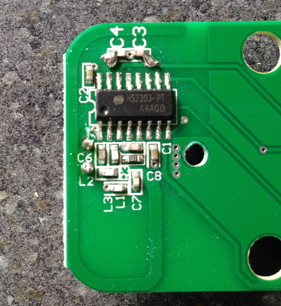
HS2302-PT chip on underside of remote PCB, could not find any datasheets on it. Lovely soldering blobs around C3 and C4 !!!
The easiest way to hook this up to Buspirate and OLS software was across the LED legs! Gnd to negative leg and CI(mask 0) to positive leg.
Note the remote code 4514 on the sticker which corresponds to this set of codes, 4514 is also stuck onto the sockets.
The output from OLS was saved as a 'value change dump .vcd' and opened in GTKWave. This is the full 7 packet repeat output of pressing button '1 on'.
Close up packet of pressing '1 on' i.e. 12363535 in binary as 101111001010011100001111 + the trailing 0 + the packet gap. It is pretty easy to see the long high short low for a 1 and opposite for a 0.
As mentioned above top, the timings varied by sampling rate in OLS for some reason - so I arbitrarily went with 50kHz sample rate values.
These were all multiples of 220;
short, 220us
long, 660us [3x220]
so each pulse is 880us
24 pulses for the code + a 0 bit = 25 * 880 = 22000us = 22 ms
interpacket gap 6380us [29x220] = 6.38 ms
whole 'send' of 7 packets = ~ 200ms
- Note the wierd timing differences in OLS are why the 7 packet sample above at 10kHz looks shorter than 200ms.
Decode table for Remote, code 4514
| Button | ON | ' | OFF | |
| Dec | Bin | |||
| 1 | 12363535 | 101111001010011100001111 | 12363534 | 101111001010011100001110 |
| 2 | 12363527 | 101111001010011100000111 | 12363526 | 101111001010011100000110 |
| 3 | 12363531 | 101111001010011100001011 | 12363530 | 101111001010011100001010 |
| 4 | 12363523 | 101111001010011100000011 | 12363522 | 101111001010011100000010 |
| ALL | 12363533 | 101111001010011100001101 | 12363532 | 101111001010011100001100 |
Notes
- Min 24 bit is 00000000000000000000001 = 1
- Max 24 bit number 111111111111111111111111 = 16'777'215
- Off is one less than On (at least for all the random numbers I tried)
- I assume a different remote 'code' will have a similar pattern for the last 4 bits too.
Step 1 Test setup receiver and sender with Raspberry PI
I bought a FS1000A transmitter and corresponding xy-mk-5v receiver on eBay for I think £2.
This is how to hook them up to the Pi. (I think the receivers data pin was at 3.3v , I should have checked, Pi ok though)
Receiver xy-mk-5v (5v)
------------------
VCC +5v pin 2 <> VCC
GND pin 6 <> GND
GPIO27 data pin 13 <> DATA
Transmitter FS1000A (3v)
-------------------
VCC 3.3v pin 1 <> VCC
GND pin 9 <> GND
GPIO 17 DATA pin 11 <> ATAD(DATA!)
I first got the sending and receiver sending a code to each other on the Pi to make sure they were wired up right using the 433Utils form Ninjablocks , which needs wiringPi
I then used the original remote with RFSniffer (receiver end) and it picked up its codes ok.
I then used codesend to control socket I had programmed with a code and it worked.
Now happy it all working ok and I know what I am doing with OLS and the bus-pirate!!
Step 2 Test Setup with FT232RL-RS232 USB Adapter
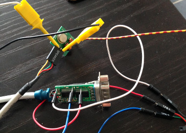
I didn't have a proper FT232R breakout board so made use of the chip from a USB <> RS232 serial adapter. (I think I bitbanged DTR and DSR pins above as they had handy through holes I could use to stick some pins in!)
I actually used LED's wired up initially rather than the FS1000A to get my head around controlling the pins to begin with.
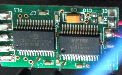
This is a legit FTDI FT232RL rev C chip with etched logo and all upper-case serial.
Well this all worked fine eventually, damn you dicky wiring! So it was time to order a FTDI board to make the final.
Building FTDI-FS1000A device
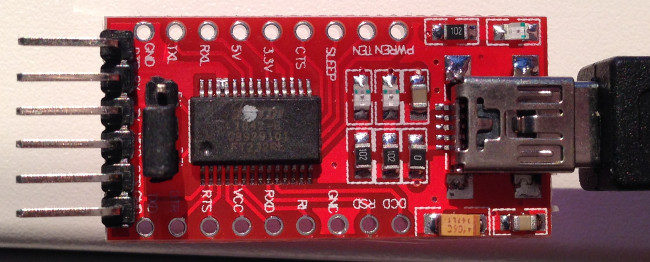
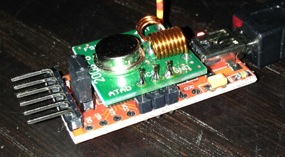
Assembling the final device. Composed of two halves, below is the FTDI board (~2£ on eBay)
This is the FT232R board featuring what I am almost 100% sure is a fake FTDI rev-B chip (logo looks printed, not etched and the serial number had lowercase characters in it!) I was rather annoyed and was sure it wouldn't work properly, however it did on the first go! Amazing!!
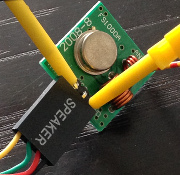
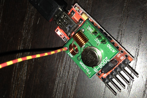
The bent pinheader was removed from the FS1000A, a straight one added to the FT232R board and then FS1000A soldered on. A nice fit!
FS1000A to FT232R
GND = GND
ATAD(DATA) = RXD
VCC(3.3V) = RI
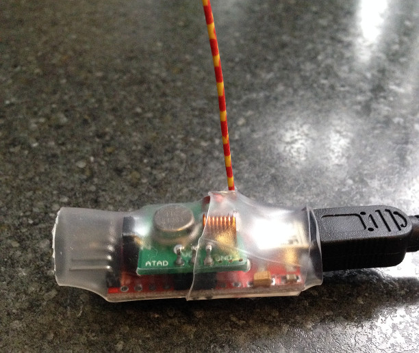
The crudest part of the build - somewhat overly thick heatshrink! Done in two halves to get around antenna from FS1000A.
Incidentally the antenna is supposed to be ~17.3cm (1/4 wavelength) for 433MHz but I think as it passes through a coil on the PCB first it should be less that. Mine seems to be 15.6cm - unfortunately I cant find the web page I came to that gave me that figure. Seems to cover at least a few metres through a wall which is more than I need for my purposes anyway.
This is final output from my little creation (two of seven packets of code 12345 above ) with almost perfect timings.
It also has more range than the original remote! The materials cost is a little less than £4 from eBay/China.
C Code
I have put code on github here
(The default bitbang pins used are for the device above, set in the DEFINE statements at the top)
/*
Depends libftdi-dev libftdi1 libusb-dev
Energenie remote code sender via FTDI bitbang
by Richud.com 2015

Default pin codes, 0x00 all off, others OR'd for on.
#define PIN_TX  0x01
#define PIX_RX  0x02
#define PIN_RTS 0x04
#define PIN_CTS 0x08
#define PIN_DTR 0x10
#define PIN_DSR 0x20
#define PIN_DCD 0x40
#define PIN_RI  0x80
*/

#include <time.h>
#include <stdio.h>
#include <limits.h>
#include <ftdi.h>

/* DEFINE are only things that should be changed */
#define DATA 0x02  /* This pin is the data line (DATA = ATAD on FS1000A, lol) */
#define VCC 0x80  /* This pin is used to power the device (VCC 3.3v) */


/* Generate a 1 or 0 pulse bit sequence and put it in array buffer */
void gen(char *buf, char **pos, int *t, char d)
{
	buf = *pos;	//set buffer array to next free row
	int x;
	for ( x = 0 ; x < *t; x++ )	//pulse
		*buf++ = d;
	*pos = buf;	//update pointer to next free row of buffer array
}

/* Convert integer to 32bit binary stored in an char array */
void dec2bin(char *dst, int x)
{
	int i;
	for (i = sizeof x * CHAR_BIT - 1; i >= 0; i--)
		*dst++ = (x >> i & 1) + '0';
}

/* Setup ftdi device */
struct ftdi_context ftdic;
void setupftdi(char **argv)
{
	ftdi_init(&ftdic); //initialize context

	if(ftdi_usb_open_desc(&ftdic, 0x0403, 0x6001, 0, argv[2]?argv[2]:0) < 0) {
		printf("Can't open device with Serial Number:%s\nTry running with sudo?\n", argv[2]);
		exit(1);
	}

	ftdi_usb_reset(&ftdic); //reset usb
	ftdi_usb_purge_buffers(&ftdic); //clean buffers
	ftdi_set_event_char(&ftdic, 0, 0); //disable event chars
	ftdi_set_error_char(&ftdic, 0, 0); //disable error chars
	ftdi_set_baudrate(&ftdic, 65536); //altering this value or moving it after setting bitbang mode will change timings!!
	ftdi_set_bitmode(&ftdic, VCC | DATA, BITMODE_BITBANG); //set bitbang mode on both pins
}


/* MAIN */
int main(int argc, char **argv)
{
	if (argc < 2) {
		puts("Usage: ./energenie code [serial]\ncode: 1 to 16777215\nserial: 8 character string");
		exit (1);
	}

	setupftdi(argv);

	char b[32]; //binary digits
	int n = atoi(argv[1]); //integer from command line
	dec2bin(b,n); //convert supplied integer to 32 bit binary

	/*
	The timings, these rely on set baudrate, 1 bit 'lasts' 4 us
	These times are 'relative' to OLS sample @ 50kHz. i.e. they changed when altering sample rate so not sure what true values are.
	They match very accurately what the remote generates, (which is about half what '433Utils/RPi_utils/codesend' produces, although both work!)
	*/
	int s = 220/4;					//short time, 220us
	int l = 660/4;					//long time, 660us [3x220]
	int g = 6380/4;					//inter packet gap, 6380us [9x220]
	int bsiz = ( 25 * (s + l) ) + g ;		//buffer size needed = 24 bits + 0 bit + interpacket gap
	char buffer[bsiz];				//buffer to send to ftdi_write_data
	char *buf = buffer;
	char *pos = buf;


	/* Generate each 24 binary digit to correct 0 or 1 pulse */
	int x;
	printf("Sending %d as ", n);
	for (x = 8; x < sizeof n * CHAR_BIT; x++) {	//24bit number so lop off first 8 0's from the 32bit dec2bin encoding
		printf("%i", b[x]-'0');			//print binary out
		if (b[x]-'0') {				/* pulse 1 */
			gen(buf, &pos, &l, VCC | DATA);	//long on
			gen(buf, &pos, &s, VCC);	//short off
		} else { 				/* pulse 0 */
			gen(buf, &pos, &s, VCC | DATA);	//short on
			gen(buf, &pos, &l, VCC);	//long off
		}
	}

	/* Generate the trailing 0 pulse, aka the 25th bit */
	gen(buf, &pos, &s, VCC | DATA);
	gen(buf, &pos, &l, VCC);

	/* Generate interpacket gap */
	gen(buf, &pos, &g, VCC);

	/* Send 7 repeat packets as per real remote */
	for ( x = 0; x < 7; x++ ) {
		ftdi_write_data(&ftdic, buf, bsiz);
	}
	puts("\nOk!\n");

	//power off xmitter
	char off = 0x00;
	ftdi_write_data(&ftdic, &off , 1);
}
README
Using an FTDI FT232R chip in BitBang mode to control a 433MHz Energenie power socket via a simple 433MHz transmitter.


This has been tested on Ubuntu 15.04 x64 and Ubuntu 14.04.2 LTS x32

Requirements
------------

An Energenie or compatible power socket.

A 433MHz transmitter such as the ubiquitous FS1000A (eBay, ~ £1)

A USB to TTL FT232RL adapter (eBay, ~ £2)

Compile
-------

sudo apt-get install libftdi-dev libftdi1 libusb-dev

git clone https://github.com/richud/energenie-bitbang.git

cd energenie-bitbang

gcc energenie.c -lftdi -o energenie

Hardware Setup
--------------
Attach Ground <> Ground

Any bitbang pin to DATA and any to VCC. (Set in energenie.c file in the #define lines.)

Usage
-----

./energenie code [serial]

e.g.

sudo ./energenie 123456 FMJ8095F

Programing it with the above code will mean 123456 switches on, 123455 off.
Example
Turn on socket with code 12345, and turn it off.
rich@PortegeR830:~/Documents/FTDI$ sudo ./energenie 12345
Sending 12345 as 000000000011000000111001
Ok!

rich@PortegeR830:~/Documents/FTDI$ sudo ./energenie 12344
Sending 12344 as 000000000011000000111000
Ok!
If you have multiple devices you may want to specify the serial, this can be found in kernel log for example
[28049.883055] usb 6-1.3.5: New USB device found, idVendor=0403, idProduct=6001
[28049.883066] usb 6-1.3.5: New USB device strings: Mfr=1, Product=2, SerialNumber=3
[28049.883072] usb 6-1.3.5: Product: FT232R USB UART
[28049.883077] usb 6-1.3.5: Manufacturer: FTDI
[28049.883082] usb 6-1.3.5: SerialNumber: A400fqa6
[28049.885655] ftdi_sio 6-1.3.5:1.0: FTDI USB Serial Device converter detected
[28049.885712] usb 6-1.3.5: Detected FT232RL
[28049.886329] usb 6-1.3.5: FTDI USB Serial Device converter now attached to ttyUSB1
This is my fake one with a funny looking serial A400fqa6
rich@PortegeR830:~/Documents/FTDI$ sudo ./energenie 12345 A400fqa6
Sending 12345 as 000000000011000000111001
Ok!
If you specify a wrong one it will error, so either use none or the correct one!
Comments
blog comments powered by Disqus
